Popular in your industry


Related Searches:


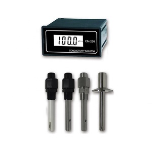
About circuit diagram conductivity meter
Understanding Circuit Diagram Conductivity Meters
Conductivity meters are essential tools in various industries, designed to measure the electrical conductivity in a solution. They are widely used in hydroponics, aquaculture, and water quality testing. A circuit diagram conductivity meter is a specific type of meter that includes a detailed circuit diagram, enabling technicians and hobbyists to understand or modify the device's functionality.
Types and Applications
There are several types of conductivity meters, each suited for different applications. Portable meters are ideal for field measurements, while benchtop models offer more features and higher accuracy for laboratory use. The conductivity meter circuit diagram is particularly useful for those who need to service or customize their meters for specific measurement tasks.
Key Features and Materials
A typical circuit diagram conductivity meter is constructed with durable materials that resist corrosion and wear. The circuitry often includes a temperature compensation feature, which is crucial for providing accurate measurements under varying temperature conditions. Understanding the conductivity meter circuit diagram allows users to identify the high-grade materials and components that contribute to the meter's reliability and longevity.
Advantages of Circuit Diagram Conductivity Meters
The main advantage of having a circuit diagram conductivity meter is the ease of troubleshooting and repair. With a clear circuit diagram, users can pinpoint issues and perform maintenance without the need for extensive technical support. Additionally, these meters often come with advanced calibration capabilities, such as multi-point calibration, to ensure precise readings.
Choosing the Right Conductivity Meter
Selecting the appropriate conductivity meter requires an understanding of the specific needs of your application. For instance, a soil conductivity meter differs from one used in water treatment. The conductivity meter circuit diagram can guide buyers in choosing a meter with the right specifications and customization options to meet their unique requirements.
Integration with Systems and Processes
Incorporating a circuit diagram conductivity meter into existing systems is straightforward when the circuit diagram is available. It allows for seamless integration with other monitoring equipment, ensuring that the conductivity meter works in harmony with the overall setup for efficient and accurate monitoring.